Sky Simulator User Manual
Sky Simulator User Manual1. Introduction1.1 Overview1.2 Features2. Concepts2.1 Space2.2 Flight2.2.1 Random Flight2.2.1.1 How Does It Work?2.2.1.2 Where to Use?2.2.2 Orbit Flight2.2.2.1 How Does It Work?2.2.2.2 Where to Use?2.2.3 Free Flight2.2.3.1 How Does It Work ?2.2.3.2 Where to Use?2.3 Sensor2.3.1 Radar Sensor2.3.1.1 What is This?2.3.1.2 How Does It Work?2.3.2 ADS-B Sensor2.3.2.1 What Is This?2.3.2.2 How Does It Work?2.4 Time2.4.1 Simulation Clock2.4.2 Running Clock2.4.3 Real Clock3. Functions3.1 Overview 3.1.1 Main Window3.1.1.1 Main Toolbar3.1.1.2 Status Bar3.1.2 Views3.1.2.1 Flight List View3.1.2.2 Sensor List View3.1.2.3 Sensor Output View3.2 Project Management3.3 Simulation Control3.4 Flight Management3.4.1 Flight Creation3.4.1.1 Random Flight3.4.1.2 Orbit Flight3.4.1.3 Free Flight3.4.2 Flight Termination3.5 Flight Control3.5.1 Transponder Operations3.5.2 Transponder Fault Simulation3.5.3 Flight Tactical Control3.6 Sensor Management3.6.1 Sensor Creation3.6.1.1 Radar Sensor3.6.1.2 ADS-B Sensor3.6.2 Sensor Removal3.6.3 Sensor Modification3.7 Settings3.7.1 Output4. File Structure and Format4.1 File Structure4.2 Project File Format4.3 Flight Database4.4 Sensor Database4.5 Environment Database5. AnnexAnnex 1. Hot-Key Combination
1. Introduction
1.1 Overview
Sky Simulator is a surveillance sensor simulation tool.
It allows you to create a simulation scenario, add different types of flights and surveillance sensors into the scenario.
When the simulation starts to run, it will simulate the flying of flights, and generate sensor output according to sensor characteristics.
The sensor output is in Eurocontrol ASTERIX format, which is industry de facto standard, and can be used by external tools and systems.
Sky Simulator was originally designed and developed to be an useful tool to test air traffic control automation system or other similar system.
1.2 Features
Sky Simulator supports the following types of flights:
Random Flight
A random flight will select a random route by itself in a predefined fly region, and fly in a random selected ground speed and level.
Orbit Flight
An orbit flight will enter an orbit route around a specified center with a specified radius.
Free Flight
A free flight will fly in the space with a starting point and specified level/speed/heading, and flight level/speed/heading could be changed manually by commands included "Flight Control" in real time.
And supports the following types of sensors:
Radar
Radar detects aircrafts by using reflection (PSR) or transponder reply (SSR), and sends out plots and/or tracks.
ADS-B
Automatic dependent surveillance - broadcast (ADS-B) receives broadcasts from aircraft transponder, assemble and send out target report.
During the simulation, it's possible to change the simulation speed, or pause it.
It's possible to check the output of selected sensor, in both raw format and decoded format.
2. Concepts
Sky Simulator tries to simulate flights and sensors the same way they behave in real world. In one simulation scenario, there are some objects and they will interact with each other.
- Space
- Flight
- Sensor
- Time
2.1 Space
Space is a three-dimensional area where flights and sensors work in.
It is equivalent to the earth surface and the space above it. All points used in simulation must be in this space, one point can be referred as a WGS-84 coordinate (aka. longitude and latitude) plus a level.
NOTE: It is not necessary to explicitly specify something like a working area, as the whole earth surface is implied in every simulation scenario.
2.2 Flight
Flights are aircrafts fly in space.
Each flight has an internal fly model, which will control how the aircraft fly, including heading, speed, level, route, etc. Each flight will fly by its own, and can go to any point in space, it doesn't care if any sensor is "observing" it.
Currently, there are three types of fly model:
- Random Flight
- Orbit Flight
- Free Flight
2.2.1 Random Flight
2.2.1.1 How Does It Work?
A random flight, as saying in its name, will fly randomly in space.
Considering the huge size of the space (whole earth surface), in reality, it's needed to set a working area and make aircraft flying only in its working area.
Once a random flight starts to run, it will randomly select two points in its working area, and fly from the start point to the end point.
When flight reach the end point, it will randomly select another point in its working area, and fly to this point.
So the route of a random flight will look like:
xxxxxxxxxx11174158N0805817E DCT 164759N0874121E DCT 185835N0810057E
And when it reaches the point 185835N0810057E, the route will automatically be extended to:
xxxxxxxxxx11174158N0805817E DCT 164759N0874121E DCT 185835N0810057E DCT 113648N0801831E
On creation of random flight, it will create initial route for at least 1 hour flying.
2.2.1.2 Where to Use?
Random flight can be used when you need to send a number of flights to external system, but don't need to seriously control the route of each flight.
This is useful when you are making generic operation/test in external system.
Another typical case is performance test and capacity test, it's easy to create 1000 flights and 32 sensors, and send all those targets to external system, to reach its capacity and check its performance in this situation.
2.2.2 Orbit Flight
2.2.2.1 How Does It Work?
An orbit flight will fly circles around a point in space.
Once an orbit flight starts to run, it will first fly from its start point to the orbit entrance point, then enter the circle orbit, after flying predefined circles, it will exit from orbit and fly to end point.
The route of an orbit flight will look like:
xxxxxxxxxx11200000N0800000E ORBIT/150000N0850000E/100/000/540 100000N0900000E
The syntax is:
xxxxxxxxxx11START_FIX ORBIT/CENTER_FIX/RADIUS/ENTER_AZIMUTH/EXIT_AZIMUTH END_FIX
After reaching end point, the orbit flight will become inactive.
2.2.2.2 Where to Use?
Circle orbit is commonly used by flight test to check surveillance equipment (e.g. radar) or navid equipment (e.g. DVOR/DME).
It is used to simulate the flight and make sure all support system works well before a real test flight departure.
2.2.3 Free Flight
2.2.3.1 How Does It Work ?
A free flight, as saying in its name, will fly freely in space.
when a free flight starts to run, it will fly with initial start_fix/level/speed/heading until someone manually changed its level/speed/heading.
Free flight will fly with its last updated level/speed/heading all the time until someone manually cancel (del) it.
The route of a free flight will look like:
xxxxxxxxxx11150000N0850000E H0000/F300N500T090
The syntax is:
xxxxxxxxxx11START_FIX TIME/LEVEL-SPEED-HEADING
A free flight will never be ended until some manually cancel (del) it.
2.2.3.2 Where to Use?
As it is very flexible, free fights are quite useful when testing some particular functions of external system. It is possible to instruct free flights to some special zones or to have a special scenario between flights to simulate those situations which are not possible to be done by real flights.
2.3 Sensor
A sensor locates in space, and observes flights flying in its view.
There are different types of sensor, such as primary radar (PSR), conventional secondary radar (SSR), Mode-S secondary radar (Mode-S), automatic dependent surveillance - broadcast (ADS-B), multilateration (MLAT), each type has its very own characteristics. Sky Simulator tries to simulate the behavior of each type of sensor as in the real world.
Each sensor has a set of properties, such as location, SAC/SIC, coverage, silent cone, detection probability, so that two sensors of the same type can have a very different view of space and observes different flights.
Currently, there are two types of sensor:
- Radar
- ADS-B
Each sensor will generate standard ASTERIX output according to its observation of flights in its view, the category of ASTERIX depends on the sensor's type.
Some sensor like ADS-B includes a property to choose which version of ASTERIX standard will be used.
2.3.1 Radar Sensor
2.3.1.1 What is This?
Radar is a detection system that uses radio waves to determine the range, angle, or velocity of objects. It can be used to detect aircraft, ships, spacecraft, guided missiles, motor vehicles, weather formations, and terrain. A radar system consists of a transmitter producing electromagnetic waves in the radio or microwaves domain, a transmitting antenna, a receiving antenna (often the same antenna is used for transmitting and receiving) and a receiver and processor to determine properties of the object(s). Radio waves (pulsed or continuous) from the transmitter reflect off the object and return to the receiver, giving information about the object's location and speed.
Secondary surveillance radar (SSR) is a radar system used in air traffic control (ATC), that not only detects and measures the position of aircraft, i.e. bearing and distance, but also requests additional information from the aircraft itself such as its identity and altitude. Unlike primary radar systems that measure the bearing and distance of targets using the detected reflections of radio signals, SSR relies on targets equipped with a radar transponder, that replies to each interrogation signal by transmitting a response containing encoded data.
2.3.1.2 How Does It Work?
The RADAR in Sky Simulator is an emulator of real world Radar.
It is installed in a location in the surface of simulation space, and receives data feeds from flights in its coverage view. Then it will assemble received information and send it out in standard ASTERIX category 001/002 or 034/048 messages.
External system could treat it as an ordinary Radar, and receive its data of simulated flights.
In real world, there are conventional radar and Mode-S radar and output of different radar types are different, which are:
- Category 001/002
- Category 034/048
Once a radar is created in simulation scenario, it is "installed" in the location specified in its parameter. the radar can be "installed" in anywhere in the space, it doesn't have to be close to the flights.
And of course, just like in real world, an radar can only observe flights in its coverage, so you cannot assume all simulated flights can be included in one radar sensor's output.
2.3.2 ADS-B Sensor
2.3.2.1 What Is This?
Automatic dependent surveillance – broadcast (ADS–B) is a surveillance technology in which an aircraft determines its position via satellite navigation and periodically broadcasts it, enabling it to be tracked. The information can be received by air traffic control ground stations as a replacement for secondary radar. It can also be received by other aircraft to provide situational awareness and allow self separation.
ADS–B is "automatic" in that it requires no pilot or external input. It is "dependent" in that it depends on data from the aircraft's navigation system.
ADS-B periodically broadcasts information about each aircraft, such as identification, current position, altitude, and velocity, through an onboard transmitter. ADS-B provides air traffic controllers with real-time position information that is, in most cases, more accurate than the information available with current radar-based systems. With more accurate information, ATC will be able to position and separate aircraft with improved precision and timing.
More information about ADS-B could be accessed from Wikipedia.
2.3.2.2 How Does It Work?
The ADS-B in Sky Simulator is an emulator of real world 1090ES ADS-B receiver.
It is installed in a location in the surface of simulation space, and receives broadcasts from flights in its coverage view. Then it will assemble received information and send it out in standard ASTERIX category 21 messages.
External system could treat it as an ordinary ADS-B station, and receive its data of simulated flights.
In real world, different ADS-B station vendors use different versions of ASTERIX category 21 formats, the simulated ADS-B supports three most commonly used ones, which are:
- Category 021 version 0.23
- Category 021 version 0.26
- Category 021 version 2.1 (Experimental)
Once an ADS-B is created in simulation scenario, it is "installed" in the location specified in its parameter. An ADS-B can be "installed" in anywhere in the space, it doesn't have to be close to the flights.
And of course, just like in real world, an ADS-B can only "see" flights in its coverage, so you cannot assume all simulated flights can be included in one ADS-B sensor's output.
2.4 Time
Time makes flights and sensors move.
There are three different clocks in the simulator:
- Simulation Clock
- Running Clock
- Real Clock
2.4.1 Simulation Clock
Simulation clock is used by flights in simulation scenario.
When a simulation starts to run, the simulation clock will start to run the same speed as the clock in real world. All flights in simulation scenario will calculate its "current" position and other fly vectors (heading, speed, level, ...) according to the "current" time in simulation clock.
User can change the speed of simulation clock to for example 5 times of real world clock. In this case, the flights in simulated world will still fly as their original speed, but from the real world observer's point of view, the flight is flying 5 times faster.
Similarly, if you change the speed of simulation clock to 1/2 of real world clock, the flights will look like moving slower.
User can pause the running of simulation clock, in this case all flights will look like frozen in its position, until the simulation clock resumes.
User can even change the simulation clock moving backwards, in this case all flights will also look like moving backwards.
2.4.2 Running Clock
Running clock is used by sensors in simulation scenario.
Once a simulation starts to run, the running clock will start to run the same sapped as the clock in real world.
User cannot change the speed or pause/resume a running clock. The running clock will stop only when the whole simulation scenario is stopped.
Sensor will run in running clock, so that no matter how you change the simulation clock, the sensor will not be affected and keep on reporting flights with the same time period as in real world.
2.4.3 Real Clock
Real clock is UTC time in our real world.
When sensor generates an ASTERIX message, it will fill timestamp with current UTC time in real world.
So that no matter when you start a simulation scenario, and no matter how the simulation clock is modified, the timestamp in transmitted ASTERIX message is always the current UTC time.
This could help external system correctly handing the messages generated by Sky Simulator. External system doesn't need to know anything of Sky Simulator and can treat it as an ordinary surveillance data source.
That's why you can use Sky Simulator to test a real ATC system by mixing simulated flights with real flights.
WARNING: Sky Simulator tries to calculate correct UTC time from OS clock and OS time zone, if OS is not properly configured, the timestamp in generated ASTERIX messages could be wrong.
3. Functions
3.1 Overview
3.1.1 Main Window
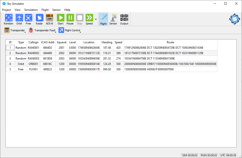
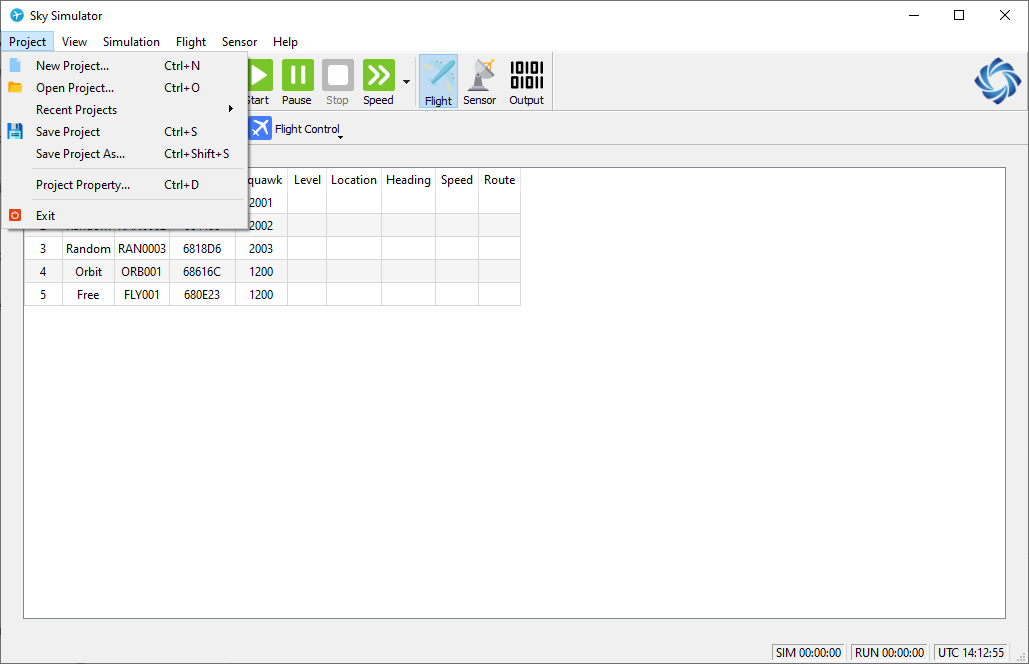
The main window of Sky Simulator is shown as below.
As a GUI application, it composes of a main menu on top, a tool bar with different buttons below the main menu, a status bar on bottom, and a switchable list view in the center.
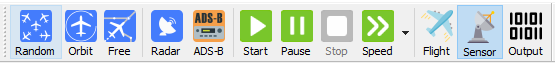
3.1.1.1 Main Toolbar
The main toolbar functions can be put into several groups.
| Tool Button | Function Group | Description |
|---|---|---|
| Random | Flight Control | Create a random flight in simulation. |
| Orbit | Flight Control | Create an orbit flight in simulation. |
| Free | Flight Control | Create a free flight in simulation |
| Radar | Sensor Control | Create a radar in simulation |
| ADS-B | Sensor Control | Create an ADS-B ground station in simulation. |
| Start | Simulation Control | Start a simulation scenario. Both simulation clock and running clock will start when this button is clicked. |
| Pause | Simulation Control | Pause or resume a simulation scenario. Only simulation clock will be paused when this button is clicked. |
| Stop | Simulation Control | Stop a simulation scenario. Both simulation clock and running clock will stop when this button is clicked. |
| Speed | Simulation Control | Change the speed of simulation clock. |
| Flight | View Switch | Switch to flight list view, all flights in simulation scenario will be shown in this view. |
| Sensor | View Switch | Switch to sensor list view, all sensors in simulation scenario will be shown in this view. |
| Output | View Switch | Switch to sensor output view, the sensor output will be displayed in this view. |
3.1.1.2 Status Bar
The status bar shows status information of the simulation.

| Item | Description | Example |
|---|---|---|
| General Message | Display general message of the application or simulation scenario | “Simulation started.” |
| Simulation Clock | Display current time of simulation clock | “SIM 05:57:45” |
| Running Clock | Display current time of running clock | “RUN 12:45:07” |
| Real Clock | Display UTC time of OS clock | “UTC 23:01:57” |
3.1.2 Views
In the center of main window, it displays switchable view. There are three views.
The detail of each view will be described in corresponding sections.
3.1.2.1 Flight List View
All flights created in simulation scenario are listed in this view. The information will update during the simulation.
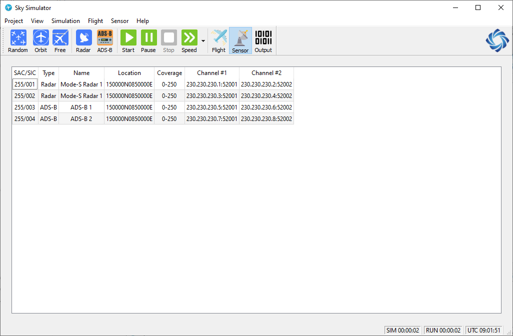
3.1.2.2 Sensor List View
All sensors defined in simulation scenario are listed in this view.
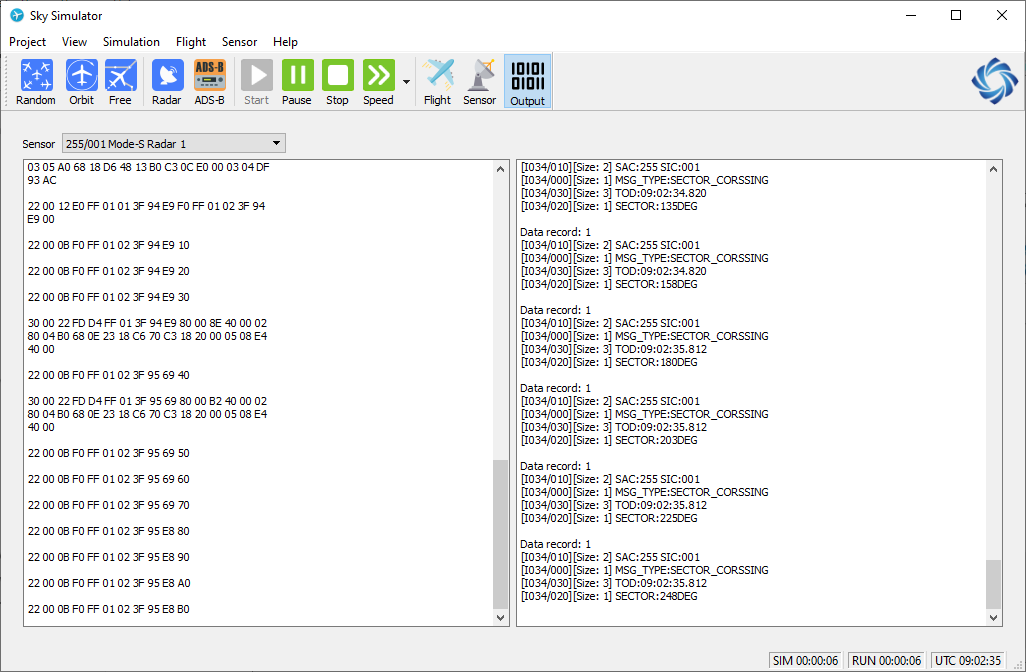
3.1.2.3 Sensor Output View
The output of selected sensor is shown in this view, both as raw format and decoded format.
3.2 Project Management
Project is like a pool contains flights, sensors and environment data defined for a particular simulated testing case.
Different projects could have different properties but share with the same flight database, sensor database and environment data.
Sky Simulator supports to create different projects, load existed projects and edit project property.
Here is a sample of options in project window .
Following are the steps to create a project.
Step 1
Man menu -> Project -> New Project;
Or press hotkey "Ctrl + N".
Open New Project Window.
Step 2
Click Ok to create a Project.
Step 3
Create some flights and sensors for this project.
Step 4
Man menu -> Project -> Save Project;
Or press hotkey "Ctrl + S".
To save the current data into current project.
Here is an example of project window:
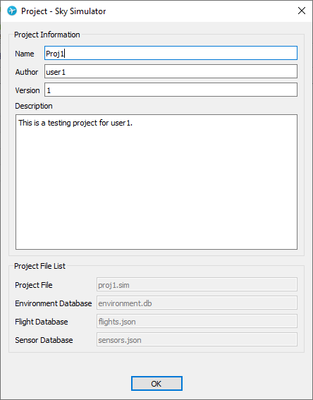
| Parameter | Description |
|---|---|
| Name | Name of project |
| Author | Author of project |
| Version | Version of project |
| Description | A short description for project |
| Project File | Project file, starts with project name, for load project |
| Environment Database | Environment data for project |
| Flight Database | flights created for project |
| Sensor Database | Sensor created for project |
3.3 Simulation Control
Simulation control can be accessed by button [Simulation] with the following three options:
Start Simulation
"Start Simulation" option could start to simulate the scenario that contained in current project.
Stop Simulation
"Stop Simulation" option is used to stop the running scenario.
Pause/Resume Simulation
A running scenario could be paused and resumed by "Pause/Resume Simulation" option.
Simulation Speed
"Simulation Speed" provides the ability to change running speed of the scenario. Speed can be changed between 0.5, 1, 2, 5 and 10 times.
3.4 Flight Management
3.4.1 Flight Creation
3.4.1.1 Random Flight
Following are the steps to create random flight.
Step 1
Man menu -> Flight -> Create Random Flights;
Or Main Toolbar -> Random;
Or press hotkey "Shift + R".
Open Random Flight Window.
Step 2
Fill parameters in Random Flight Window.
Click Check to make sure all parameters are correct.
Step 3
Click Create to create a number of random flights.
Step 4
In Main Window, switch to Flight List View, check random flights are created.
Here is a sample of Random Flight Window.
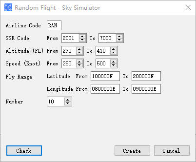
And the meaning of each parameter is listed below.
| Parameter | Description | Format | Example | Note |
|---|---|---|---|---|
| Airline | The airline ICAO code | [A-Z]{3} | DLH | This parameter will be used as the first three letters of callsign, a 4-digit number will be automatically attached to form the callsign of each flight |
| SSR Code | The SSR code range of flights | [0-7]{4} | 1277 | System will try to find and assign a non-duplicated code in this range, but if not possible, any code in this range could be assigned |
| Altitude | Flight level range, unit is flight level, or 100 feet | [0-9]{3} | 320 | System will assign a random level in this range |
| Speed | Ground speed range | [0-9]{3} | 400 | System will assign a random ground speed in this range |
| Fly Range | Working area of flights | DDMMSS[N/S] DDDMMSS[E/W] | 0455933E | The route of flight will be limited in this range |
| Number | Number of flights will be created | [0-9]+ | 15 | Range 1-1000. Each flight will randomly select its own SSR, level, speed, Mode-S address, ... |
3.4.1.2 Orbit Flight
Following are the steps to create orbit flight.
Step 1
Man menu -> Flight -> Create Orbit Flights;
Or Main Toolbar -> Orbit;
Or press hotkey "Shift + O".
Open Orbit Flight Window.
Step 2
Fill parameters in Orbit Flight Window.
Click Check to make sure all parameters are correct.
Step 3
Click Create to create an orbit flight.
Step 4
In Main Window, switch to Flight List View, check orbit flight is created.
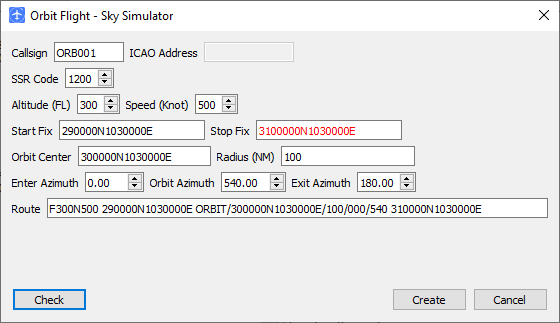
Here is a sample of Orbit Flight Window.
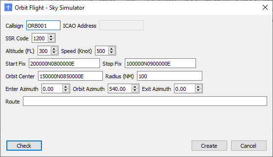
And the meaning of each parameter is listed below.
| Parameter | Description | Format | Example | Note |
|---|---|---|---|---|
| Callsign | The callsign of flight | [A-Z]{3}[0-9]{1,4} | DLH1923 | |
| ICAO Address | The Mode-S address | [0-9|A-F]{6} | 6830C9 | System will assign a random Mode-S address which is not used by any other flight |
| SSR Code | The SSR code of flight | [0-7]{4} | 1277 | System will not check if code is duplicated or not |
| Altitude | Flight level, unit is flight level, or 100 feet | [0-9]{3} | 320 | |
| Speed | Ground speed | [0-9]{3} | 400 | |
| Start Fix | The start point where flight will first appear | DDMMSS[N/S]DDDMMSS[E/W] | 200000N0800000E | |
| Stop Fix | The stop point where flight will finish | DDMMSS[N/S]DDDMMSS[E/W] | 100000N0900000E | |
| Orbit Center | The center of circle orbit | DDMMSS[N/S]DDDMMSS[E/W] | 150000N0850000E | |
| Radius | The radius of circle orbit | [0-9]{3} | 100 | |
| Enter Azimuth | The azimuth in degree where flight will enter circle orbit | [0-9]+(\.[0-9]{1,2})? | 5.00 | Range 0.00 - 359.99 |
| Orbit Azimuth | The azimuth in degree the flight will fly in circle orbit | [0-9]+(\.[0-9]{1,2})? | 540.34 | |
| Exit Azimuth | The azimuth in degree where flight will exit circle orbit | [0-9]+(\.[0-9]{1,2})? | 184.34 | This filed is not mandatory, it will be calculated when clicking Check button |
| Route | The route of orbit flight | This filed is not mandatory, it will be calculated when clicking Check button |
After clicking the Check button, system will check all parameters and field with error will be marked with red color.
3.4.1.3 Free Flight
Following are the steps to create free flight.
Step 1
Man menu -> Flight -> *Create Free Flights;
Or Main Toolbar -> Free;
Or press hotkey "Shift + F".
Open Free Flight Window.
Step 2
Fill parameters in Free Flight Window.
Click Check to make sure all parameters are correct.
Step 3
Click Create to create a free flight.
Step 4
In Main Window, switch to Flight List View, check free flight is created.
Here is a sample of Free Flight Window.
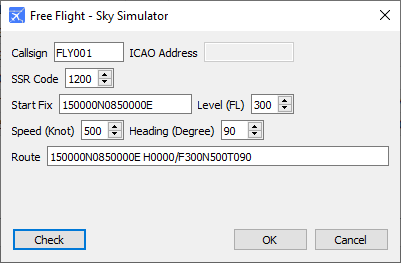
| Parameter | Description | Format | Example | Note |
|---|---|---|---|---|
| Callsign | The callsign of flight | [A-Z]{3}[0-9]{1,4} | DLH1923 | |
| ICAO Address | The Mode-S address | [0-9|A-F]{6} | 6830C9 | System will assign a random Mode-S address which is not used by any other flight |
| SSR Code | The SSR code of flight | [0-7]{4} | 1277 | System will not check if code is duplicated or not |
| Start Fix | The start point where flight will first appear | DDMMSS[N/S]DDDMMSS[E/W] | 200000N0800000E | |
| Level | Flight level, unit is flight level, or 100 feet | [0-9]{3} | 320 | |
| Speed | Ground speed | [0-9]{3} | 400 | |
| Heading | Flight heading | [0-9]{3} | 90 | Range 0 - 360 |
| Route | The route of orbit flight | This filed is not mandatory, it will be calculated when clicking Check button |
3.4.2 Flight Termination
In "Flight List View" window, a selected flight can be terminated at any time of simulation process by:
- Click on "Flight"->"Terminate Flight" button;
- or press hotkey "Del".
Once a flight is terminated, it will be removed from "Flight List Window" and Sky Simulator will also remove it from output data block.
3.5 Flight Control
In the flight view, there is an additional sub-toolbar to provide an access to give the instructions/commands for different type of flights.

With these functions, variable of scenarios could be simulated to meet the testing requirements that are needed for testing different functions of external system.
Note: To give the instruction/command for a certain flight, this flight must be selected in flight view.
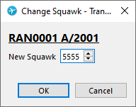
3.5.1 Transponder Operations
Here below list options included in "Transponder Operations":
Change Squawk
SSR code of the selected flight could be changed through following window.
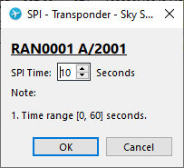
SPI
Sky Simulator could enable SPI for a selected flight, maximum duration up to 60 seconds.
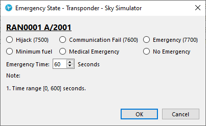
Emergency State
Sky Simulator trigger the emergency state for a selected flight, maximum duration up to 600 seconds.
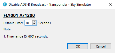
Disable ADS-B Broadcast
ADS-B broadcast could be disabled for up to 600 seconds.
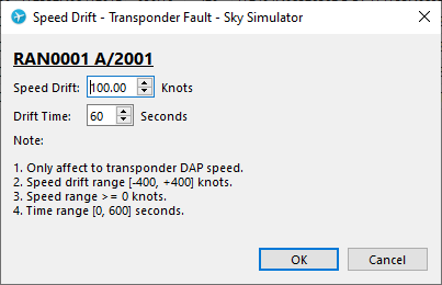
3.5.2 Transponder Fault Simulation
Here below list the options include in "Transponder Fault":
Speed Drift
Sky Simulator cold simulate a speed jump for a ADSB target.
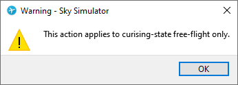
3.5.3 Flight Tactical Control
"Flight Control" only works on "Free Flight", if other flights with fly model orbit or random are selected, when operate on flight control, Sky Simulator will give a warning like the window below.
Here below list the options include in "Flight Control":
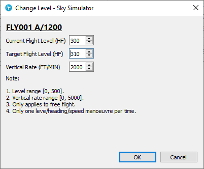
Change Level
Level of flight can be changed by the window below.
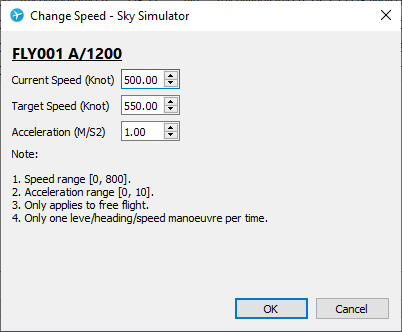
Change Speed
Speed of flight can be changed by the window below.
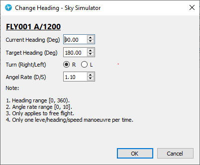
Change Heading
Heading of flight can be changed by the window below.
3.6 Sensor Management
3.6.1 Sensor Creation
3.6.1.1 Radar Sensor
Following are the steps to create RADAR.
Step 1
Man menu -> Sensor -> Create Radar;
Or Main Toolbar -> Radar.
Open Radar Window.
Step 2
Click Create to create a Radar.
Step 3
In Main Window, switch to Sensor List View, check Radar is created.
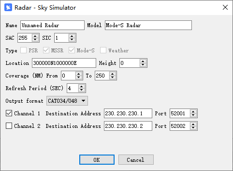
Here is a sample of Radar Window.
| Parameter | Description | Format | Example | Note |
|---|---|---|---|---|
| Name | Name of Radar | Free text | Mode-S Radar | |
| Model | Model of Radar | SinoATC Mode-S Radar | Model is used to emulate product characteristic from different vendors. | |
| SAC/SIC | SAC and SIC code | [0-9]{1,3} | 197 | Range 0 - 255. Each sensor must have a unique SAC/SIC in one simulation scenario |
| Type | Type of Radar | Check different options to output different types of data | ||
| Location | Location of Radar | DDMMSS[N/S]DDDMMSS[E/W] | 150000N1030000E | |
| Coverage | Minimum and maximum coverage | [0-9]{1,3} | 250 | |
| Refresh Period | Period to update all flights in its view | [0-9]{1,2} | 4 | Range 1 - 10 |
| Output Format | The format that will be used to encode ASTERIX message | CAT0001/002 CAT034/048 | ||
| Channel | If output channel is activated | If both channels are deactivated, no message will be transmitted even there are flights in ADS-B’s view | ||
| Destination Address | IP address | 230.230.230.1 | Must be a valid multicast, broadcast or unicast address | |
| Port | Port number | 52001 | Range 1 - 65535 |
3.6.1.2 ADS-B Sensor
Following are the steps to create ADS-B station.
Step 1
Man menu -> Sensor -> Create ADS-B;
Or Main Toolbar -> ADS-B.
Open ADS-B Ground Station Window.
Step 2
Click Create to create an ADS-B ground station.
Step 3
In Main Window, switch to Sensor List View, check ADS-B ground station is created.
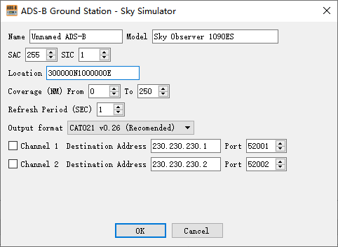
Here is a sample of ADS-B Window.

And the meaning of each parameter is listed below.
| Parameter | Description | Format | Example | Note |
|---|---|---|---|---|
| Name | Name of ADS-B ground station | Free text | My ADS-B | |
| Model | Model of ADS-B | SinoATC 1090ES ADS-B Receiver | Model is used to emulate product characteristic from different vendors. | |
| SAC/SIC | SAC and SIC code | [0-9]{1,3} | 197 | Range 0 - 255. Each sensor must have a unique SAC/SIC in one simulation scenario |
| Coverage | Minimum and maximum coverage | [0-9]{1,3} | 250 | |
| Refresh Period | Period to update all flights in its view | [0-9]{1,2} | 2 | Range 1 - 10 |
| Output Format | The format that will be used to encode ASTERIX message | CAT021 v0.26 | ||
| Channel | If output channel is activated | If both channels are deactivated, no message will be transmitted even there are flights in ADS-B’s view | ||
| Destination Address | IP address | 230.230.230.1 | Must be a valid multicast, broadcast or unicast address | |
| Port | Port number | 52001 | Range 1 - 65535 |
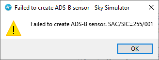
After clicking the Create button, system will check all parameters, if any error is detected, an error message will be shown.
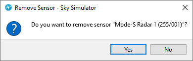
3.6.2 Sensor Removal
In "Sensor List View" window, a selected sensor can be removed when the simulation is stopped by:
- Click on "Sensor"->"Remove Sensor" button;
- Or press hotkey "Shift + Del".
3.6.3 Sensor Modification
In "Sensor List View" window, a selected sensor can be edited when the simulation is stopped by:
- Click on "Sensor"->"Edit Sensor ..." button;
3.7 Settings
3.7.1 Output
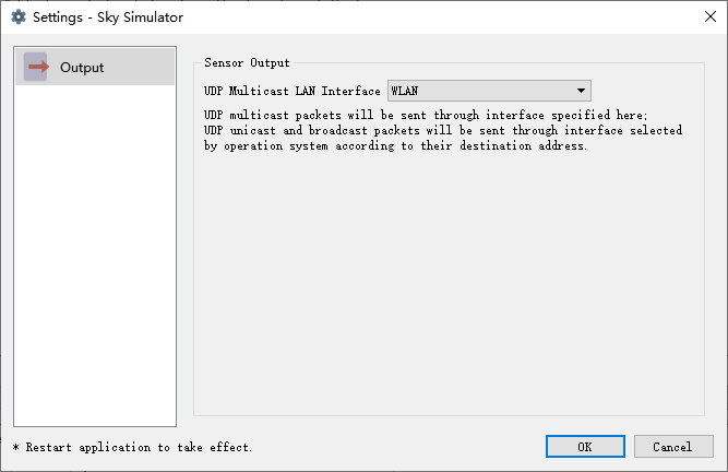
| Setting | Description |
|---|---|
| UDP Multicast LAN Interface | UDP multicast packets will be sent through interface specified here; UDP unicast and broadcast packets will be sent through interface selected by operation system according to their destination address. |
4. File Structure and Format
4.1 File Structure
When saving a project into hard drive, different information in a simulation session will be saved into different files.
Files in a typical project looks like:
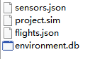
Project file (*.sim)contains project information and references to other files used in this project. The name of this file is the one you entered when saving a new project for the first time.
Flight database (flights.json) contains all flights created in simulation session.
Sensor database (sensors.json) contains all sensors created in simulation session.
Environment database (environment.db) contains airspace environment data used by flights in simulation session.
4.2 Project File Format
Project file is an INI format plain text file. You can open it with any text editor such as vi or notepad.exe.
The content of a project file looks like:
xxxxxxxxxx101[meta]2name=A Sample Project3author=Donald Trump4version=1.05description=Flights to simulate flight test.67[files]8environment=environment.db9flight=flights.json10sensor=sensors.json4.3 Flight Database
Flight database is a JSON format plain text file. You can open it with any text editor such as vi or notepad.exe.
The content of a flight database file looks like:
xxxxxxxxxx421[2 {3 "callsign": "FLY001",4 "icaoaddr": "6804ea",5 "model": {6 "heading": 90,7 "level": 25000,8 "speed": 300,9 "start": "302828N1035636E"10 },11 "squawk": "2401",12 "type": "free"13 },14 {15 "callsign": "RAN0001",16 "icaoaddr": "68022d",17 "model": {18 "altitude": 30000,19 "northeast": "343806N1084640E",20 "southwest": "261652N0990739E",21 "speed": 33122 },23 "squawk": "2001",24 "type": "random"25 },26 {27 "callsign": "ORB001",28 "icaoaddr": "681015",29 "model": {30 "altitude": 30000,31 "center": "302828N1035637E",32 "enter-azimuth": 180,33 "orbit-azimuth": 720,34 "radius": 100,35 "speed": 450,36 "start": "265646N1041251E",37 "stop": "265646N1041251E"38 },39 "squawk": "2500",40 "type": "orbit"41 }42] WARNING: Please do NOT modify this file unless you are sure what are you doing. A corrupted flight file will not be loaded by Sky Simulator, and you may lost all flights created before.
4.4 Sensor Database
Sensor database is a JSON format plain text file. You can open it with any text editor such as vi or notepad.exe.
The content of a sensor database file looks like:
xxxxxxxxxx401[2 {3 "ch1": true,4 "ch1_addr": "224.0.10.11",5 "ch1_port": 20021,6 "ch2": false,7 "ch2_addr": "230.230.230.2",8 "ch2_port": 52002,9 "coverage": 250,10 "format": "cat21v0.26",11 "interval": 1,12 "location": "113117N0102007E",13 "min_coverage": 0,14 "name": "Test ADS-B",15 "sac": 16,16 "sic": 11,17 "type": "adsb"18 },19 {20 "ch1": true,21 "ch1_addr": "224.0.10.1",22 "ch1_port": 20011,23 "ch2": false,24 "ch2_addr": "230.230.230.2",25 "ch2_port": 52002,26 "format": "cat48",27 "location": "102828N0095636E",28 "modes": true,29 "name": "Test Radar",30 "psr": false,31 "rotation_period": 4,32 "sac": 16,33 "sectors": 16,34 "sic": 19,35 "ssr": true,36 "ssr_coverage": 250,37 "ssr_min_coverage": 0,38 "type": "radar"39 }40] WARNING: Please do NOT modify this file unless you are sure what are you doing. A corrupted sensor file will not be loaded by Sky Simulator, and you may lost all sensors created before.
4.5 Environment Database
Environment database is a SQLite 3 database file, you can use any SQLite compatible database management tool to open it.
It contains essential airspace data used by flights using ICAO IFR fly model in simulation session.
NOTE: Environment database is not included in current version of Sky Simulator.
5. Annex
Annex 1. Hot-Key Combination
Project Management Hotkeys
Here below describes those hotkeys for project management.
| Key Combination | Function |
|---|---|
| Ctrl + N | Create new project |
| Ctrl + O | Open a project |
| Ctrl + S | Save current project |
| Ctrl + Shift + S | Save current project as |
| Ctrl + D | Open project property |
Simulation Management Hotkeys
Here below describes those hotkeys for simulation management.
| Key Combination | Function |
|---|---|
| F5 | Start simulation |
| Shift + F5 | Stop simulation |
Flight Management Hotkeys
Here below describes those hotkeys for flight management.
| Key Combination | Function |
|---|---|
| Shift + R | Create random flights |
| Shift + O | Create orbit flights |
| Shift + F | Create free flights |
| Del | Delete selected flight (In flight view) |
Sensor Management Hotkeys
Here below describes the hotkey for sensor management.
| Key Combination | Function |
|---|---|
| Shift + Del | Delete selected sensor (In sensor view) |