Sky Converter User Manual
Sky Converter User ManualOverviewIntroductionApplicabilityCopyrightsGetting StartedConceptsReceiverProcessorDispatcherModifierConverterTransmitterMain windowMain ToolbarViewsInput ViewConversion ViewOutput ViewMessagesConfigurationDisplayInputDispatchModifierSAC/SIC ModifierTimestamp ModifierFake Distress Squawk SuppressionConversionOutputASTERIXLAN
Overview
Introduction
Sky Converter is a Mode-S & Mode-A/C radar format converter.
Sky Converter receives plots and/or tracks from radar, modifies data contents and converts data formats according to predefine rules, and then distributes to downstream users.
Sky Converter is typically used as a radar front end processor, and can be used in scenarios listed below:
- Integrating new Mode-S radar into existing ATM systems which doesn't supports Mode-S formats, by converting data from Mode-S formats into Mode-A/C formats.
- Modifying data fields in original radar data, such as SAC/SIC and timestamp.
- Detect and fix erroneous data fields in original radar data, which are usually caused by problems of radar itself, such as fake TCAS alerts and fack distress SSR code.
- Filter unneeded data from specific source or in specific category for downstream system.
Applicability
This document is based on Sky Converter version 1.x.
Copyrights
Sky Converter is a product of SinoATC, please contact info@sinoatc.com for more information.
Getting Started
Concepts
Sky Converter in general has three modules: receiver, processor and transmitter.
Receiver receives input data from upstream system, such as PSR, SSR or ASR.
Processor modifies and/or converts radar data according to predefined rules.
Transmitter sends output data to downstream systems.
Receiver
Receiver works with LAN interfaces and uses UDP multicast protocol.
It receives message from LAN and send it to processor for further processing.
User can specify hardware interface, multicast address and UDP port in configuration.
Legacy interface like RS232/HDLC can also be supported by using Serial-LAN adaptor.
Processor
Processor is the core module of Sky Converter, it decodes, modifies and converts data packets received from Receiver, and send generated data packets to transmitter.
Processor consists of three components: dispatcher, modifier, and converter.
Dispatcher
When a message is received from LAN, receiver will remove all headers used by low level protocols, and send message payload (we call it data packet) to dispatcher.
Dispatcher will try to decode and extract ASTERIX data block from data packet.
For each extracted ASTERIX data block, three actions would be applied according to configuraiton.
Process
Data block will be send to Modifier for further processing.
Bypass
Data block will be sent to Transmitter for output, no any modification will be applied on data block.
Discard
Data block will be dropped, no further action will be made.
Different action can be applied per each ASTERIX category, so this function can also be used to filter out unneeded categories for downstream system.
Modifier
Data block eligible for "process" will be decoded to a series of data records. Each data record will be sent to Modifier for further processing.
Modifier is like a pipeline, it has a series of sub-modifiers, data record will be sent to each sub-modifier and processed one by one.
Each sub-modifier has specific function, and will modify (or not modify) data record according to predefined configuration. The output of first sub-modifier is the input of the second sub-modifier.
Once a data record has passed all sub-modifiers, it will get out of pipeline, and be sent to converter.
Modifier works on data record, it may modify content of data data record but it will not change category of data record.
In current version of Sky Converter, following sub-modifiers has been implemented.
SAC/SIC modifier
Change SAC/SIC value in data record to a new one.
This can be used to fix incorrect SAC/SIC in original radar without having to change settings in radar.
It is also useful when integrating both original data and modified data into a same downstream system.
Timestamp modifier
Change timestamp in data record to current UTC time.
This is useful when injecting recorded data into a system for processing.
Fake distress squawk suppression
Detect fake distress squawk in data stream and change it back to normal code or mark it to garbled.
This is used to detect and suppress fake distress squawk from some Selex radars, which can cause unnecessary fake hijack, communication fail and emergency alerts in ATM system.
Converter
Converter receives data record from modifier, convert it to another category, and send it to transmitter.
For each ASTERIX category, different conversion actions can be selected, by in general there are two actions.
Passthrough
Data recorder will not be converted and will passthrough converter untouched.
Convert
Data recorder will be converted to another category.
Transmitter
Transmitter works with LAN interfaces and uses UDP multicast protocol.
It obtains ASTERIX data records from processor, assembles them into ASTERIX data block, and sends data block to LAN.
Transmitter can send one ASTERIX data block to up to ten (10) destinations.
User can specify hardware interface, multicast address and UDP port in configuration.
Legacy interface like RS232/HDLC can be also supported by using LAN-Serial adaptor.
Main window
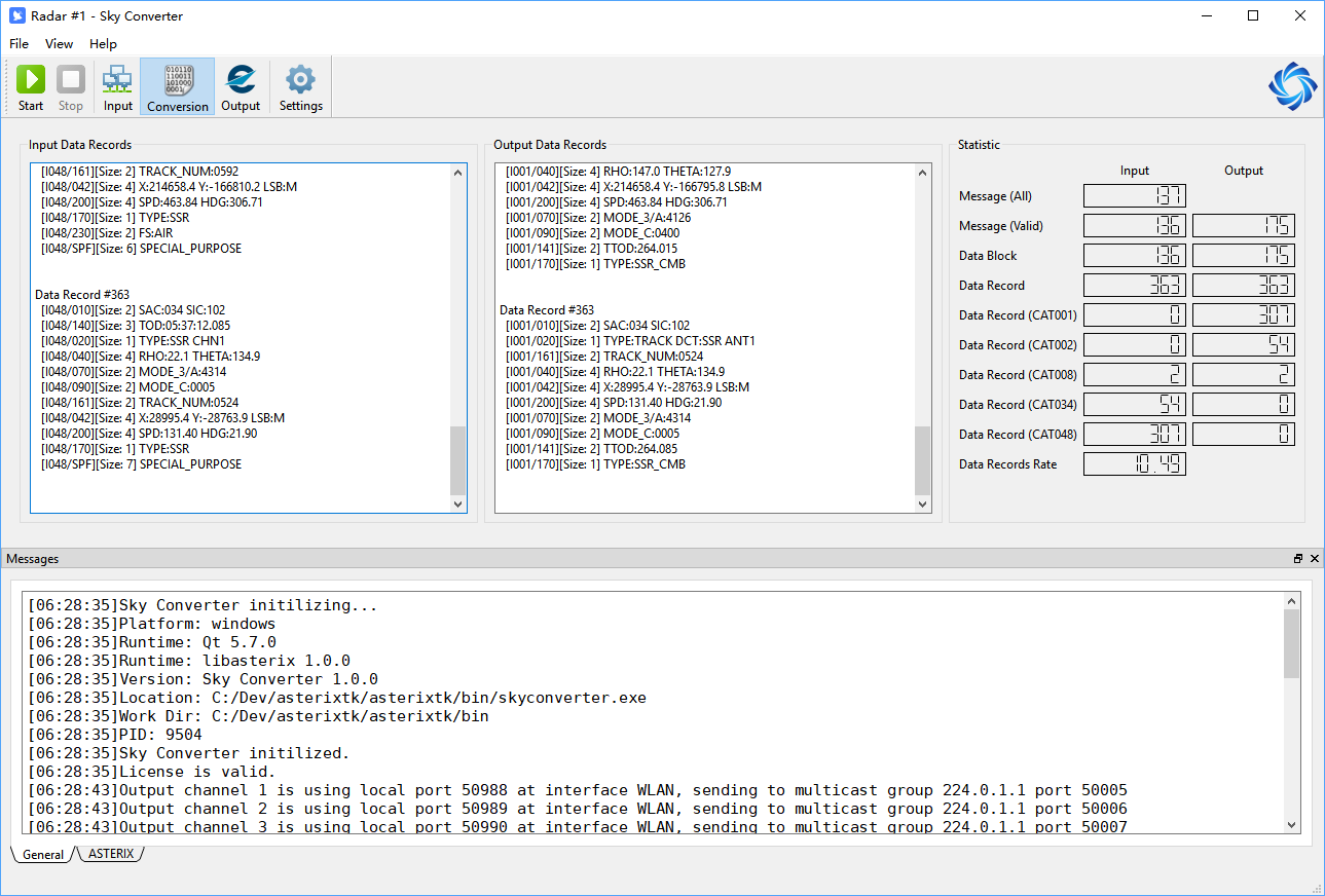
The main window of Sky Converter is shown as below.
As a GUI application, it composes of a main menu on top, a tool bar with different buttons below the main menu, a status bar on bottom, and switchable views in the center.
Main Toolbar
The main toolbar functions can be put into several groups.

| Tool Button | Function Group | Description |
|---|---|---|
| Start | Process Control | Start processing. |
| Stop | Process Control | Stop processing. |
| Input | View Switch | Switch to input message view, original messages received is shown in this view. |
| Conversion | View Switch | Switch to conversion view, data records sending to pipeline and out of pipeline will be shown in this view. |
| Output | View Switch | Switch to output message view, processed messages will be displayed in this view. |
Views
In the center of main window, it displays switchable view. There are three views.
Input View
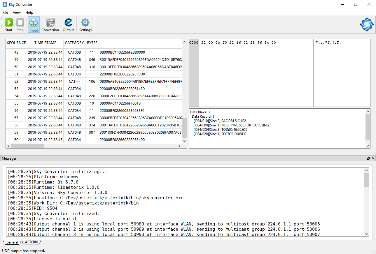
All messages received from LAN will be shown here, if received message contains ASTERIX data and can be correctlly decoded, the decoded message will also be shown in this view.
Conversion View
All data records eligible for processing will be shown in this view.
On the left it shows original data records beforing entering processor.
In the middle it shows processed data records output from processor.
Statistical information is displayed on the right.
Output View
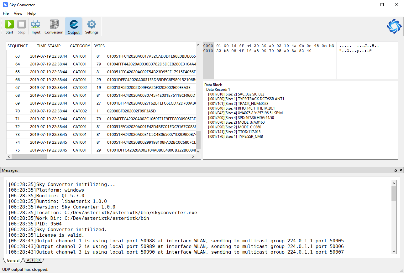
Assembled data blocks and data packets are shown in output view, they will be sent to LAN to external systems.
Messages
At the bottom of main window, there is a message window showing systems messages.
This window can be closed.
Configuration
Display
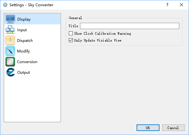
Title
A free text can be filled in this field, it will be displayed in the title bar of main window, and also in OS desktop components (e.g. Windows taskbar). It helps user to distinguish when multiple instances are running.
Show Clock Calibration Warning
When selected, a warning message will be shown before stat processing.
Some system functions relies on host computer system clock, it is used as a reminder.
Only Update Visible View
When selected, only the UI of current visible view will be updated.
This is used to reduce system load.
Input
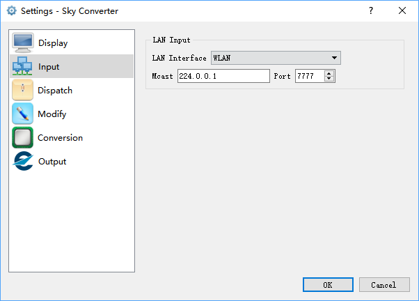
LAN Interface
Physical LAN interface which will be used to receive messages.
The interfaces are reported by OS and only active interfaces supporting multicast are listed here.
Mcast
Multicast address of input messages.
System will join this group after starting process.
Port
UDP port of input messages.
System will listen on this port after starting process.
Dispatch
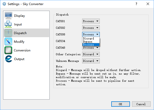
Dispatch
Dispatch actions for each category of data block.
Three actions can be selected for each category.
Process
Data block will be send to Modifier for further processing.
Bypass
Data block will be sent to Transmitter for output, no any modification will be applied on data block.
Discard
Data block will be dropped, no further action will be made.
Categories not listed will apply to action specified in "Other Categories".
Undecodable message will apply to action specified in "Unknown Message" and always be dropped.
Modifier
Modify settings include several pages, one per each sub-modifier.
- SAC/SIC Modifier
- Timestamp Modifier
- Fake Distress Squawk Supression
SAC/SIC Modifier
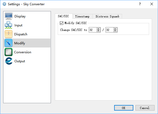
Modify SAC/SIC
This sub-modifier will be enabled when selected.
Change SAC/SIC to ??/??
New SAC and SIC that will be used.
Timestamp Modifier
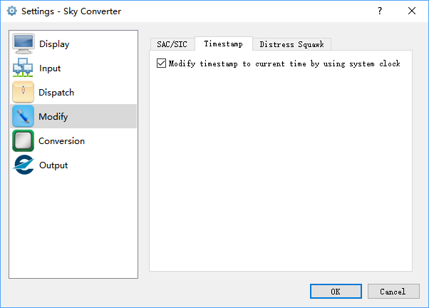
Modify timestamp to current time by using system clock
This sub-modifier will be enabled when selected.
Fake Distress Squawk Suppression
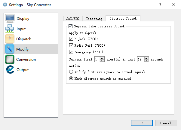
Suppress Fake Distress Squawk**
This sub-modifier will be enabled when selected.
Apply to Squawk
Only selected squawk will be detected and suppressed, including
- 7500 Hijack
- 7600 Radio Fail
- 7700 Emergency
Suppress first ? alerts in last ? seconds
System will apply suppression action to first data records in a period, this is used to avoid suppressing real distress squawk.
Typical setting is to suppress first 1 alert in 3 radar rotations (12 seconds or 15 seconds).
Action
Suppression actions.
Modify distress squawk to normal squawk
Squawk in data record will be modified to the last received non-distress squawk from this track.
Mark distress squawk as garbled
Squawk in data record will not be modified but its garble-bit will be set to 1.
Conversion
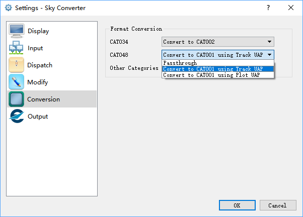
Format Conversion
Data record conversion actions for each category.
CAT034
Passthrough
Data recorder will not be converted and will passthrough converter untouched.
Convert to CAT002
Mode-S radar CAT034 data record will be converted to conventional radar CAT002 data record, standard UAP will apply.
CAT048
Passthrough
Data recorder will not be converted and will passthrough converter untouched.
Convert to CAT001 using Track UAP
Mode-S radar CAT048 data record will be converted to conventional radar CAT001 data record, standard track UAP will apply.
Convert to CAT001 using Plot UAP
Mode-S radar CAT048 data record will be converted to conventional radar CAT001 data record, standard plot UAP will apply.
Other Categories
Passthrough
Data recorder will not be converted and will passthrough converter untouched.
Output
Output settings include several pages.
ASTERIX
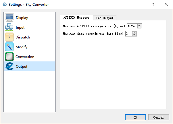
Maximum ASTERIX message size
Maximum size of each data block.
When a new data record is created, if current data block has enough space to hold it, it will assembled into current data block. If current data block has no enough space, data block will be sent out, and data record will be assembled into a new data block.
Maximum data records per data block
Maximum number of data records in one data block.
When a new data record is created and assembled into current data block, if number of data records in this data block has reached maximum number specified here, the data block will be immediately sent out.
LAN
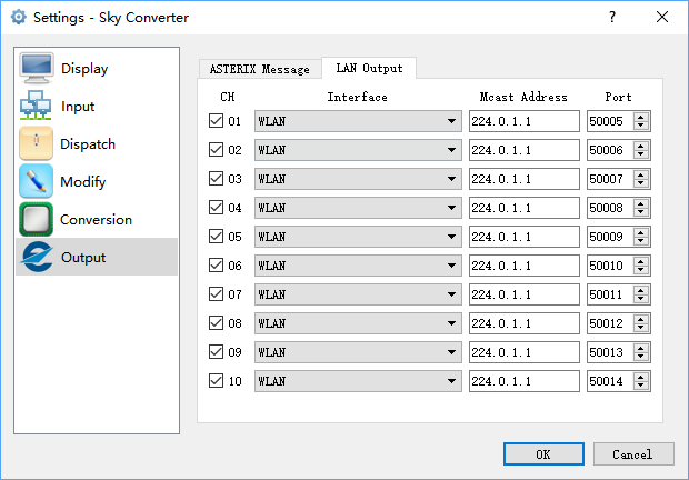
CH
Message will be sent to selected channels.
Interface
Physical LAN interface which will be used to send messages.
The interfaces are reported by OS and only active interfaces supporting multicast are listed here.
Mcast
Multicast address to send messages.
System will join this group after starting process.
Port
UDP port to send messages.